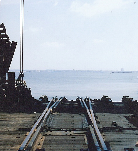
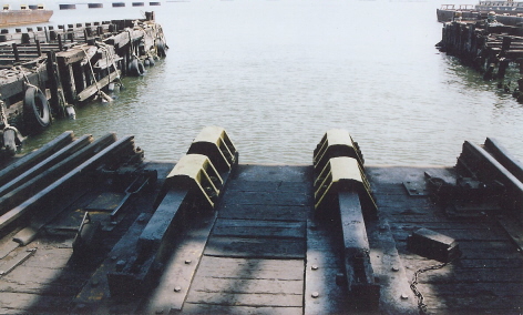
Carfloat and Floatbridge Anchoring Mechanisms
Carfloat Mooring & Pinning Procedures
(Carfloat & Floatbridge Pins, Toggles and Binding Wheels)
Please
note:
not shown are track appurtenances;
i.e.: frogs, turnouts, guardrails, etc.
DIAGRAMS NOT TO SCALE
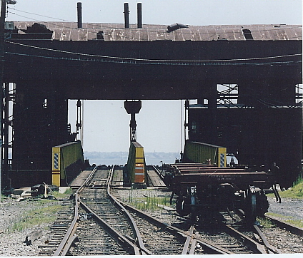
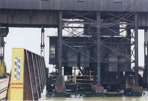
The illustration below shows the appliances found on almost all pontoon type float bridges used throughout New York Harbor. Clicking on the illustration below will bring you to close up off the appliances. Use the back arrow on your web browser to return you here.
Please take note that the only appliance not shown is the float bridge jack and a-frame. The reason for this is that this component has not been used in day to day float bridge operations for the last 20 years. Matter of fact, by referencing current images of New York New Jersey Rail float bridge operations in Brooklyn, the float bridge jack is not even mounted on the Bush Terminal float bridge in service.
This appliance, if it were to have been included in the diagram below, would have been located between the center two toggles with the hydraulic piston overhanging from the edge of the float bridge.
DIAGRAM NOT TO SCALE
 |
.
.
Carfloat Mooring & Float Bridge Pinning Procedures
..This chapter, once the reader has familiarized themselves with the components of a floatbridge; is to give the reader an understanding of the procedures involved in mooring and pinning a carfloat to a float bridge.
To moor carfloats at pontoon type float bridges;
the following procedure applies:
Tugboat approaches float bridge with carfloat, and holds it in position for mooring;
Four hawser lines attached to front mooring
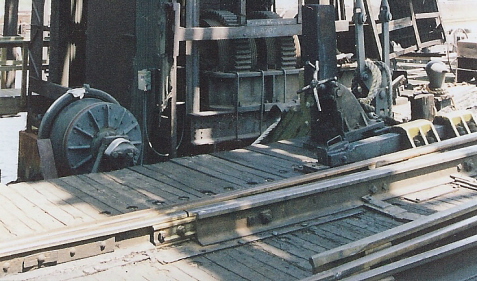
cleats (two on each side) of carfloat and are tightened up via winch wheels
to bring carfloat into initial
alignment. The winch wheels turns the winch drum (which
holds the hawser line) via a gear reduction / torque multiplier system;
Locomotive slowly proceeds onto right track (facing water) of float bridge to weigh it down into the water; and to match height of float bridge with deck of carfloat;
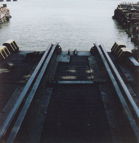
The right toggle bars are slid into carfloat receptacles and fastened with the toggle block;
Hawser lines would be tightened again via winch wheels, and mooring lines from carfloat side cleats are attached to finger pier (if applicable);
Locomotive reverses and backs off float bridge, switches to left track,
and proceeds forward on float bridge left track until left side toggle bars
are aligned with carfloat toggle receptacles;
The left toggles (pins) are slid into carfloat receptacles and fastened with the chock;
Hawser lines are tightened again;
Hand jacks on the rails on the float bridge would be turned to adjust the horizontal alignment of the rails on the float bridge to match with rails on carfloat;
Locomotive now "drills" (unloads cars from carfloat). For the procedure
on this operation, please proceed to the next chapter below:
"Carfloat Unloading Procedures"
Carfloat mooring and pinning procedures
were a little different at electrically operated (separate apron & contained
apron) type float bridges; as those float bridges has electric winches for
drawing in the carfloat tight against the float bridge:
Tugboat brings carfloat in, and the float bridge
is raised or lowered by bridgeman in control cabin to bring it into correct
height alignment with
carfloat.
Hawser lines from power winch attached to front mooring cleats on each side of carfloat.
Carfloat would be drawn in tight to float bridge.
All toggles (pins) would be slid into carfloat receptacles and chocked in.
Secondary hawser lines from manually powered winch wheels added and tightened.
Hawser lines from carfloat side cleats attached to "finger piers" on both sides of carfloats.
Hand jacks on the rails on the float bridge
would be turned to adjust the horizontal alignment of the rails on the float
bridge to match with rails on
carfloat;
Locomotive now "drills" (unloads cars from carfloat). For the procedure on
this operation, please proceed to the next chapter below:
"Carfloat Unloading Procedures"
.
.
Carfloat Unloading a/k/a "Drilling" Procedures
Please note:
|
Locomotive is inched forward onto float bridge to
bring it into same height as carfloat. Carfloat is secured to float bridge
using method and appliances outlined in above
chapter. Locomotive then couples up to cut of cars on starboard
side track.
Locomotive pulls cut of cars on starboard side track
half way off the carfloat and onto the float bridge lead; leaving part of
the cut of cars still on
float bridge and carfloat;
The locomotive uncouples from starboard side cut of cars, and locomotive continues past float bridge lead turnout. Turnout is thrown and aligned for port side track.
Locomotive heads forward onto port side carfloat track, and couples up to cut of cars on port side track.
Locomotive reverses direction, and pulls entire cut of cars off of port side track of carfloat and past float bridge lead turnout; and float bridge lead turnout is thrown and aligned for starboard side track.
Locomotive proceeds forward pushing port side cut of cars and couples up to starboard side cut of cars.
Locomotive reverses direction and pulls combined port and starboard side cuts of cars off carfloat to clear the turnout on float bridge for carfloat center track, and points of center track turnout are thrown and aligned for center track;
Locomotive pushes combined port and starboard of cars onto carfloat, coupling up to string of cars on the center track of carfloat.
Locomotive reverses direction, and pulls entire cut
of cars (combined port starboard and center track cuts of cars) into
the yard.
Carfloat is now unloaded. To load carfloat, reverse procedure.

Would you like to see this operation in real time? Visit my videos on YouTube at:
.
.
.
Pictures of former BEDT floatbridge located in Greenville, NJ
(still in use by NY Cross Harbor Railroad)
|
| x
x x |
|
| x
x x |
|
| x
x x |
|
| x
x x |
|
| x
x x |
|
| x
x x |
|
Return To Main BEDT
page: |
Return
To |